Button Hat Hardware Modification Guide
Required for Basic PCB V2 and Advanced PCB with Button Hat purchased in 2025 - Firmware dated November 11, 2025 or later
🛠️ Materials Needed
- Soldering iron (temperature controlled, 350-400°C recommended)
- Wire cutters or flush cutters
- Jumper wire - CRITICAL: 22-24 AWG, exactly 25mm (1 inch) long
- Solder (lead or lead-free)
- Helping hands or PCB holder (optional but helpful)
- Multimeter (optional, for testing continuity)
Skill Level: Basic soldering experience required
Time Required: 10-15 minutes
Step 0: Understand the Pin Layout
Before starting, familiarize yourself with the QT Py SAMD21 pinout. You'll be working with pins A3 and A8 on the bottom row of the board.
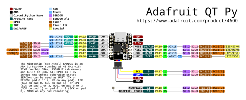
Important pins to identify:
- A3 - Currently connected to button hat, needs to be disconnected
- A8 - New button input pin, needs connection from A3
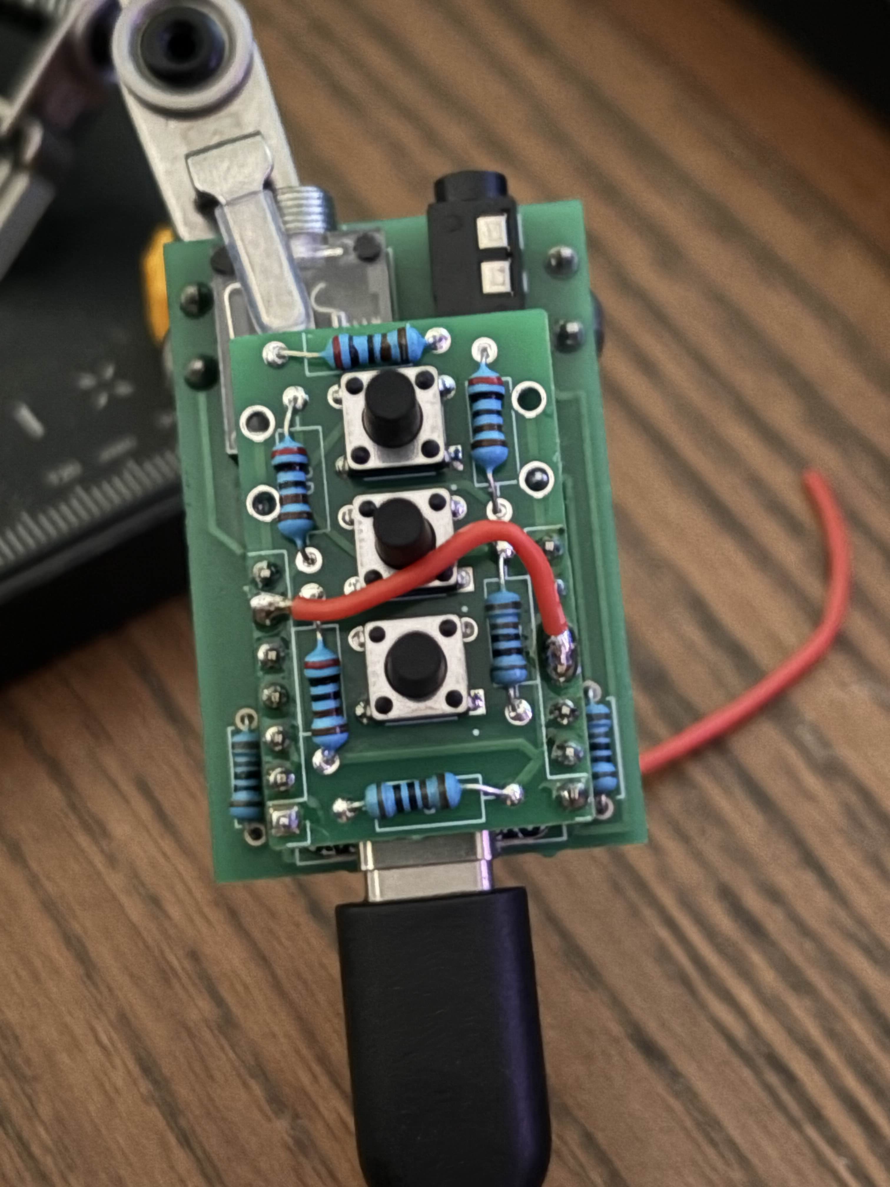
Step 1: Cut the A3 Header Pin
The first step is to disconnect the button hat's A3 connection from the QT Py board.
Procedure:
- Remove power: Ensure your Vail Adapter is completely unplugged from USB
- Identify pin A3: Locate the A3 header pin on the underside of the QT Py board (where the pins connect to the PCB)
- Cut the pin: Using wire cutters, carefully cut the A3 header pin between the QT Py board and the PCB
- Leave enough pin length on the QT Py side to solder a wire to (about 2-3mm)
- This disconnects the button hat from the old pin location
- Verify the cut: Gently wiggle the QT Py board to confirm pin A3 is no longer physically connected
Step 2: Solder Jumper Wire from A3 to A8
Now you'll create a new connection from the button hat signal (A3 pin on button hat side) to the new button input (A8 on the QT Py).
Procedure:
- Prepare the wire: Cut a jumper wire to exactly 25mm (1 inch) length and strip both ends
- Important: Wire length must be 25mm for proper button calibration
- Use 22-24 AWG solid core wire for best results
- Tin both ends: Apply a small amount of solder to both ends of the wire
- Solder to A3 pad: On the PCB side (where the button hat connects), solder one end of the wire to the A3 pad/pin stub
- This is the button hat side that was just disconnected
- The signal needs to come from the button hat to route to the new pin
- Route the wire: Run the wire along the bottom of the board toward pin A8
- Solder to A8 pin: Solder the other end of the wire to the A8 header pin on the QT Py side
- A8 is located on the bottom edge of the QT Py (see pinout diagram)
- Make sure you have a good solder connection with electrical continuity

Step 3: Test Your Modification
After completing the modification, test to ensure everything works correctly.
Testing Procedure:
- Visual inspection: Check that:
- A3 pin is fully cut and disconnected
- Jumper wire has good solder joints at both A3 and A8
- No solder bridges between adjacent pins
- Continuity test (optional): Use a multimeter to verify:
- Continuity between button hat A3 pad and QT Py A8 pin
- No continuity between button hat A3 and QT Py A3
- Flash firmware: Return to the firmware updater and flash the latest firmware
- Test buttons: After flashing:
- Press each button (B1, B2, B3) individually to verify detection
- Test combo presses (B1+B2, B1+B3, B2+B3)
- Buttons should respond reliably without double-triggering
❓ Troubleshooting
Buttons don't respond at all
- Check that jumper wire has good solder connections at both ends
- Verify continuity between button hat A3 pad and QT Py A8 pin with multimeter
- Ensure you flashed the latest firmware (November 11, 2025 or newer)
- Check that the button hat ribbon cable is fully seated
Buttons trigger erratically or give wrong values
- Verify jumper wire is exactly 25mm long - incorrect length is the most common cause of erratic button behavior
- Check for solder bridges between A8 and adjacent pins
- Verify A3 pin on QT Py side is fully disconnected from PCB
- Ensure jumper wire is not shorting to other components
- Try reflashing the firmware to reset calibration
One specific button doesn't work
- This is likely a button hat resistor issue, not related to the modification
- Test with the button troubleshooting sketch to verify resistor values
- Check button hat solder joints for the non-working button
📞 Need Help?
If you run into issues or have questions about this modification:
- Email: ke9bos@pigletradio.org
- Discord: Join the Vail community Discord for real-time assistance (link in the GitHub repository)
- GitHub Issues: Report bugs or request clarification at github.com/Vail-CW/vail-adapter
Photos of your setup can be very helpful for troubleshooting - feel free to include them when reaching out!